Passive Solar

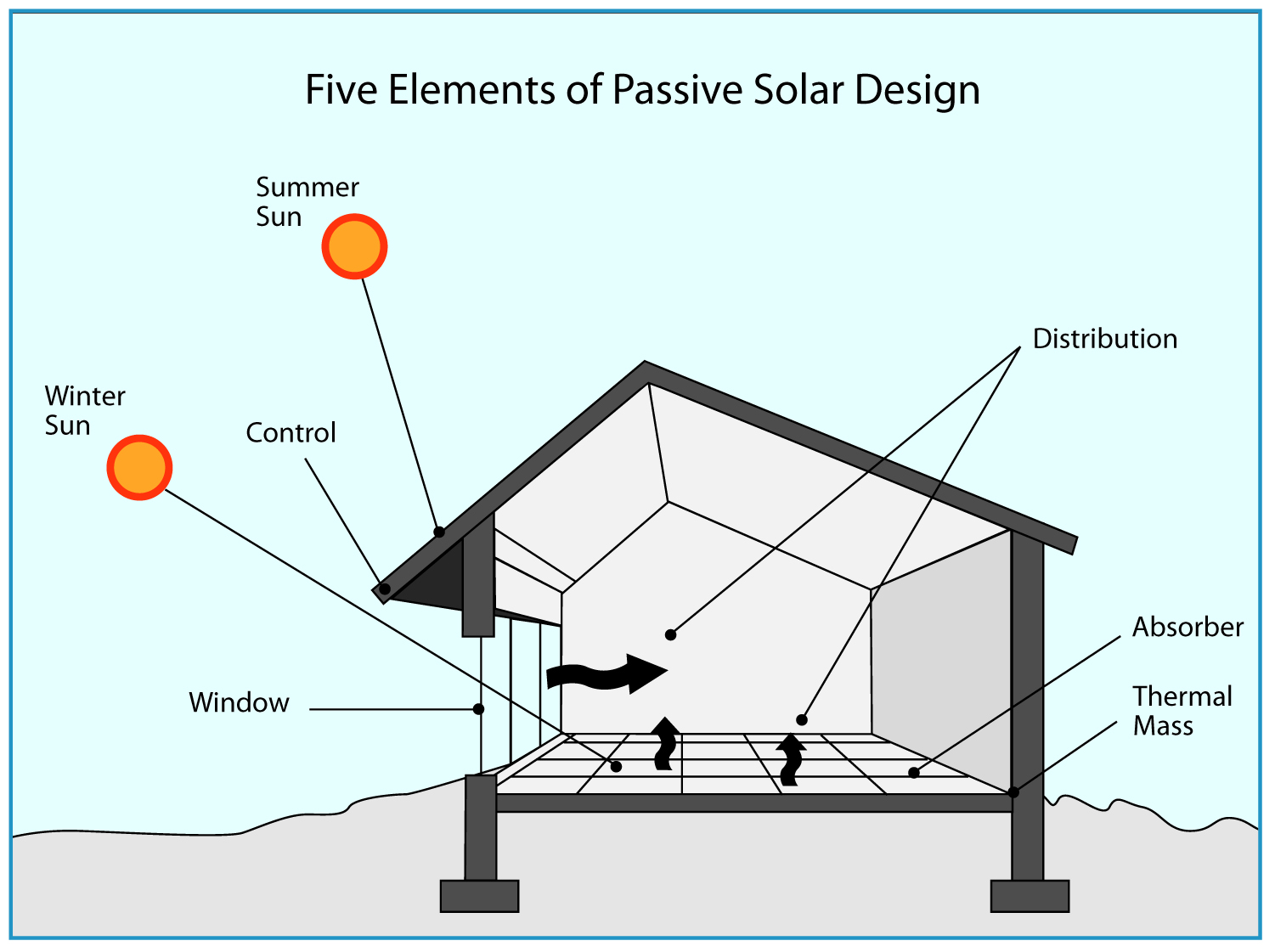
Passive Solar refers to a design strategy by which a house harvests the winter sunlight for heating. Because the sun is much lower in the sky during winter months (solar elevation is 22 degrees in winter but 67 degrees in summer), carefully calculated roof overhangs can allow south facing windows to be exposed to the sun during winter months, yet remain shaded during summer months. A thermal mass (usually in the form of a concrete floor or wall) is used to store the heat from the sunlight, which it then radiates as indoor temperatures begin to cool off at night.

How to use passive solar design to improve your home's natural lighting and regulate temperature for indoor comfort.
The basic principles of Passive Solar design

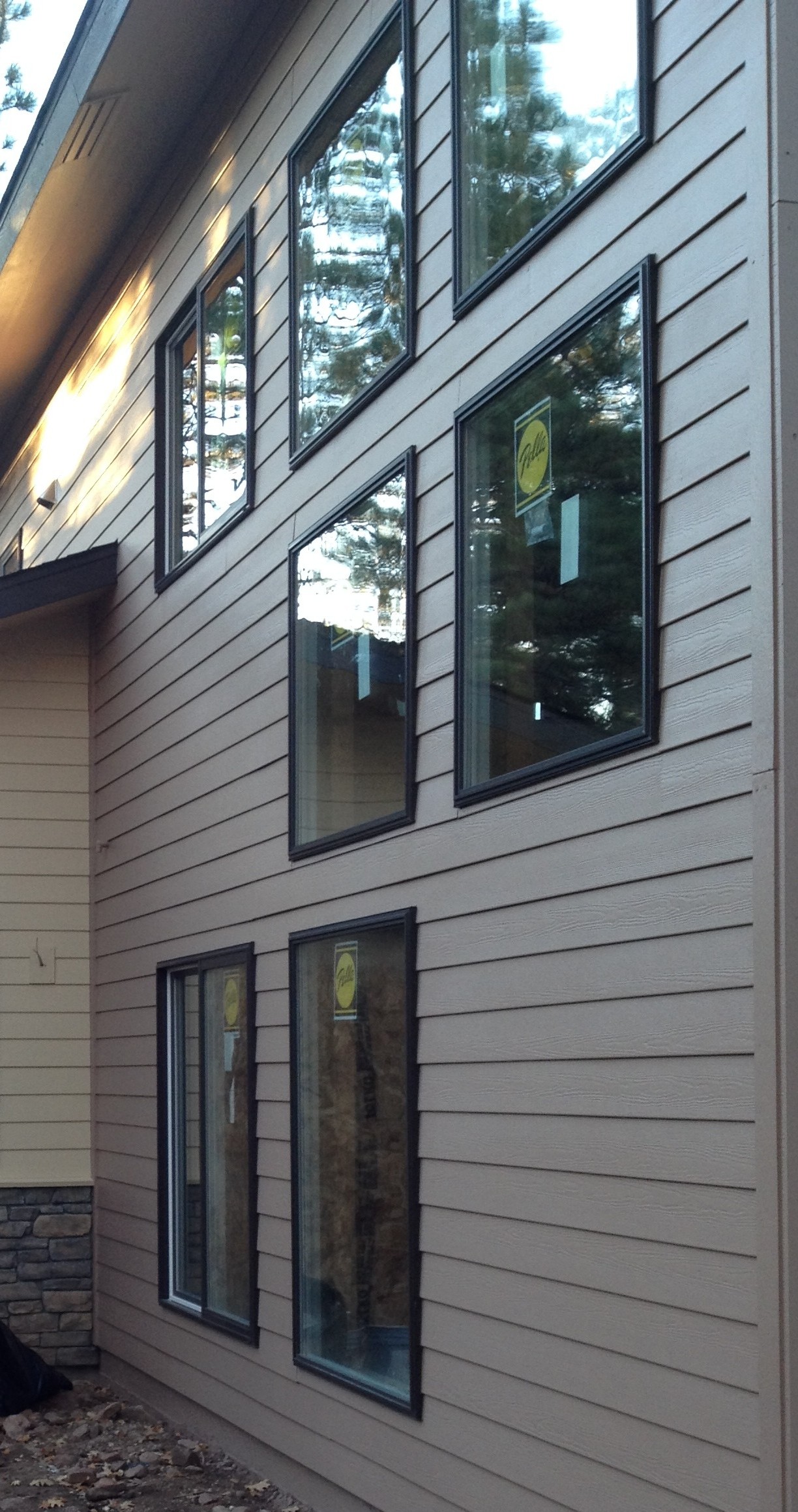
My site location did not allow me to contemplate a completely passive solar design. I had to account for many days (or weeks) in a row of cloudy or snowy weather. Also, I had pine trees partially obscuring the sun in winter months. However, I did try to incorporate passive solar elements in order to reduce the amount of mechanical heating the house would require. It also allowed me to include a large bank of windows on the southern facade with no “energy penalty”. Although my windows were R5 (good for a window), they have almost no insulating value when compared to my walls at R37. But with the added heating benefit of winter sunlight, they made up for this deficiency in insulation value. So 41% of my glazing is on the south wall.

sketchup_shade
Using SketchUp and Google Earth, I was able to model exact shading at any time of day, and any day of the year.

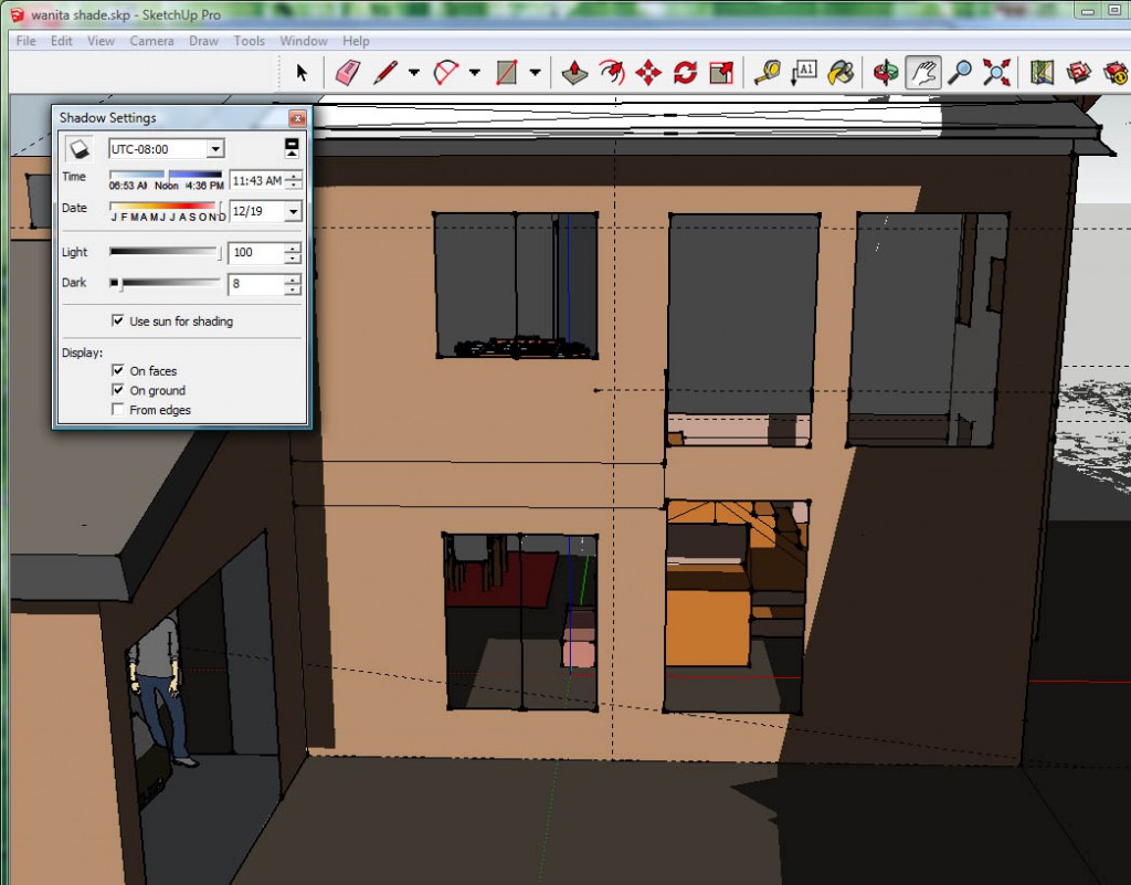
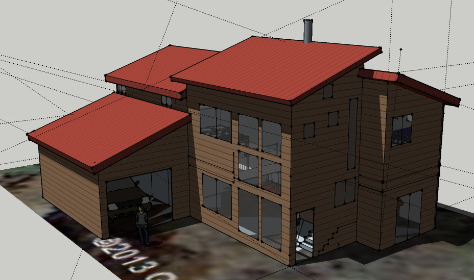
In order to position windows and design an effective roof overhang, I designed a simple model of the house using a CAD program called Sketchup. Then, by “placing” the model on its exact location inside Google Earth, I was able to see how the sunlight entered through windows at various times of the day during different months. This allowed me to carefully position windows and size the roof overhang above them to achieve optimal sun exposure.

Windows

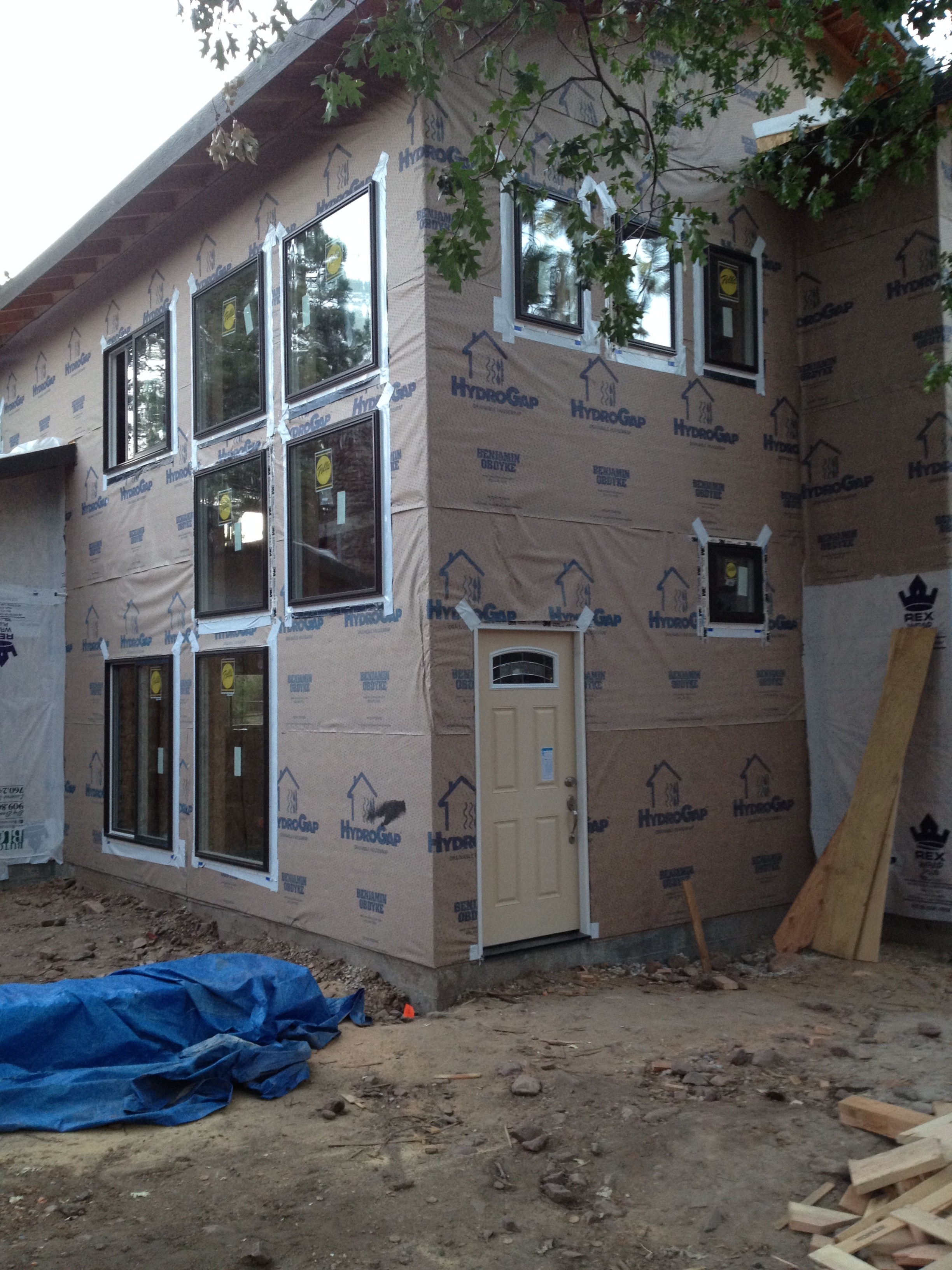
Window glass is naturally transparent to visible light and high frequency solar radiation (ie, heat). However, these days most energy efficient windows have special Low-e coatings that reflect heat, so they keep the heat from the sun out, and the heat from the house in. I selected a special glass coatings for the windows on the south facade with high Solar Heat Gain Coefficients (0.62 center of glass measurement), to allow as much solar heat through the windows as possible. This coating still reflects low frequency radiation back into the house, yet is mostly transparent to high frequency solar radiation
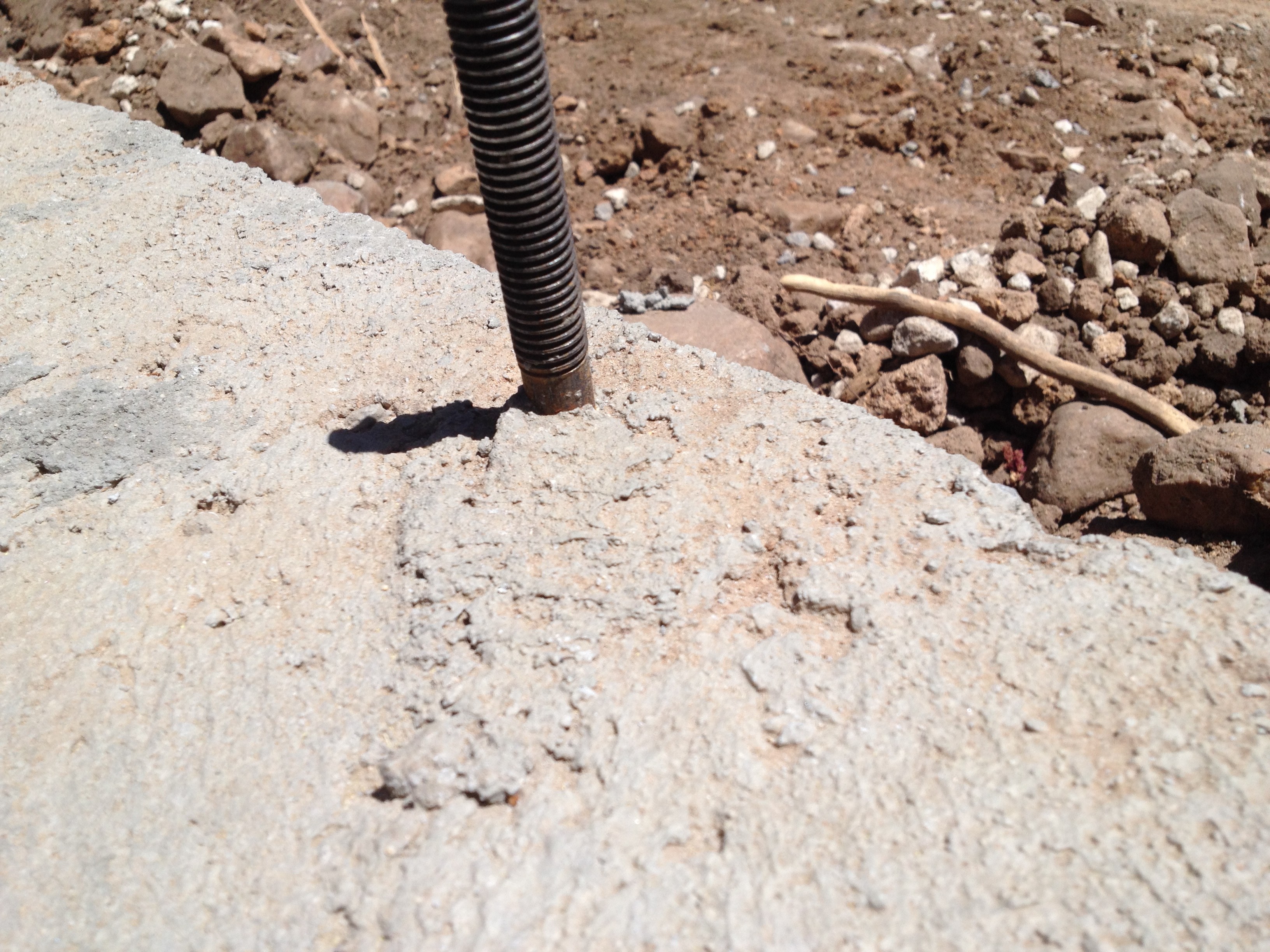
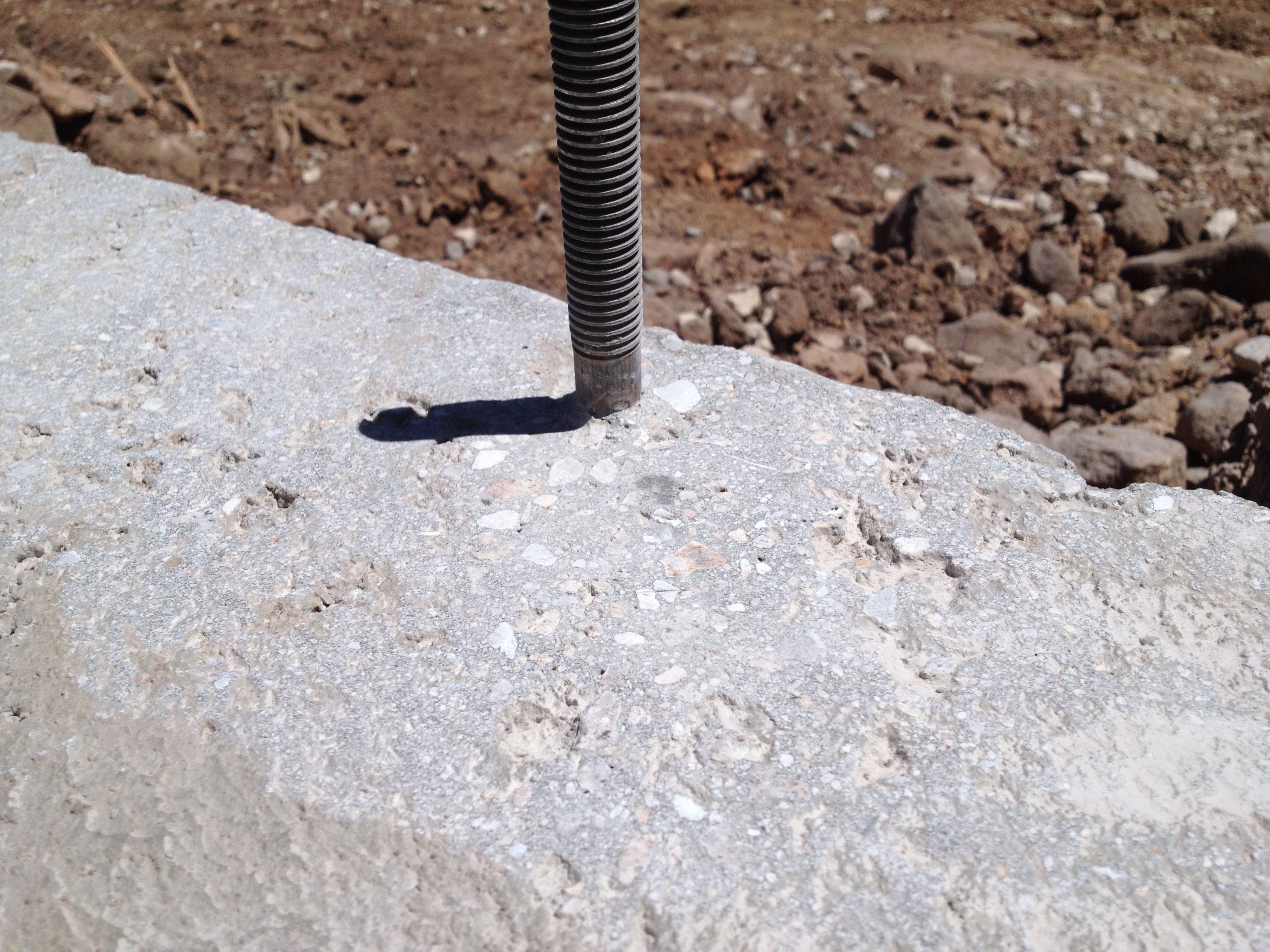
Thermal Mass

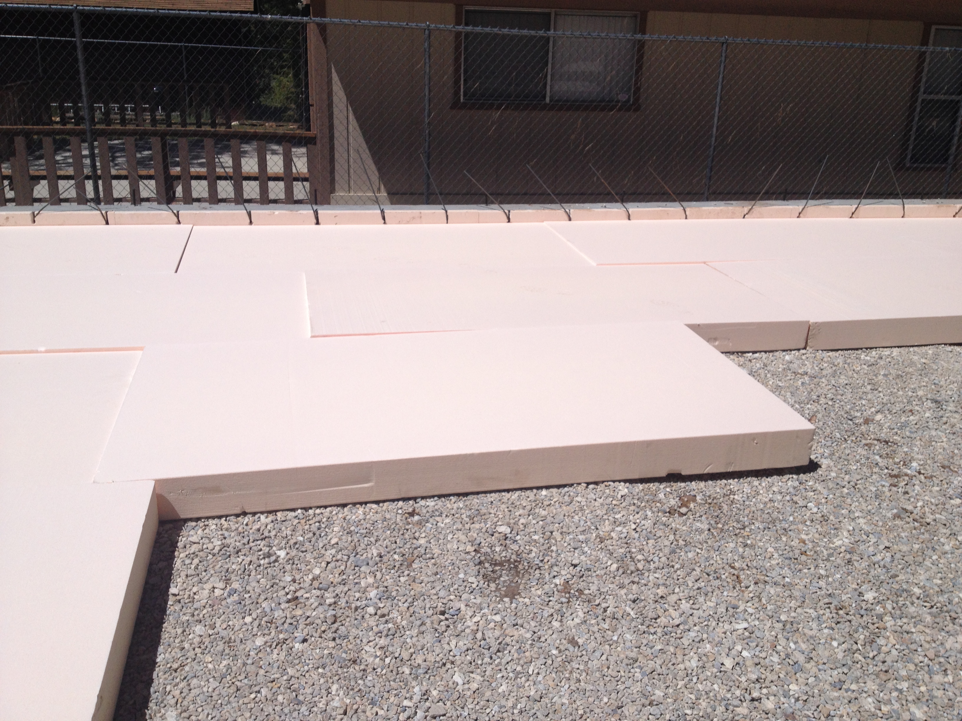
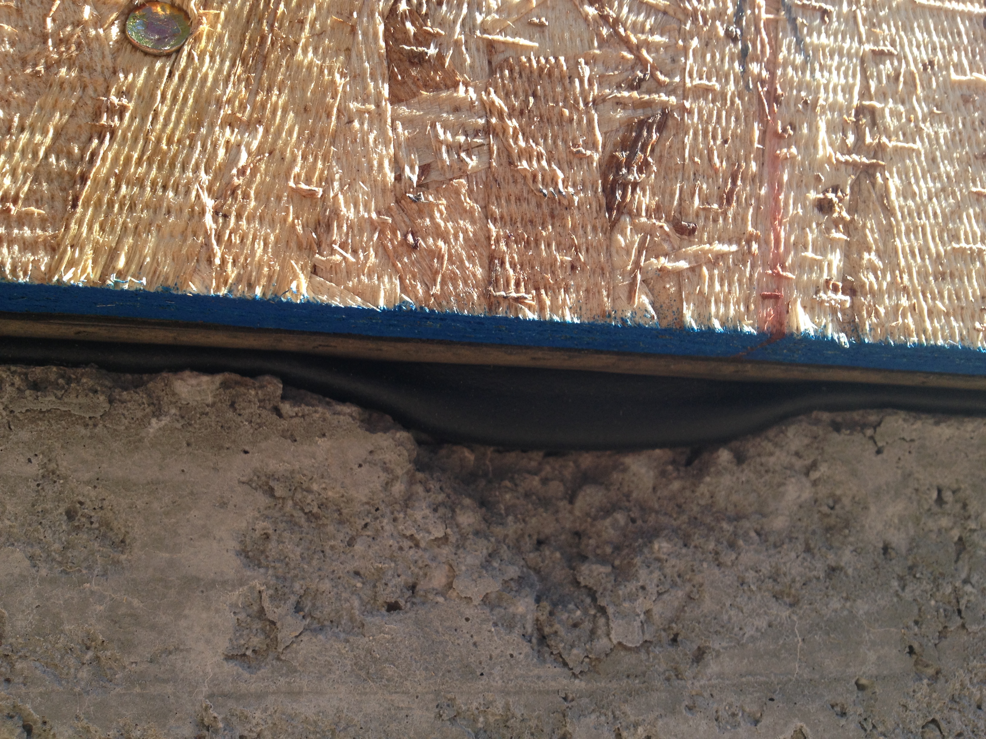
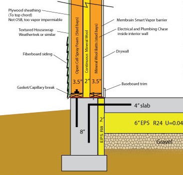
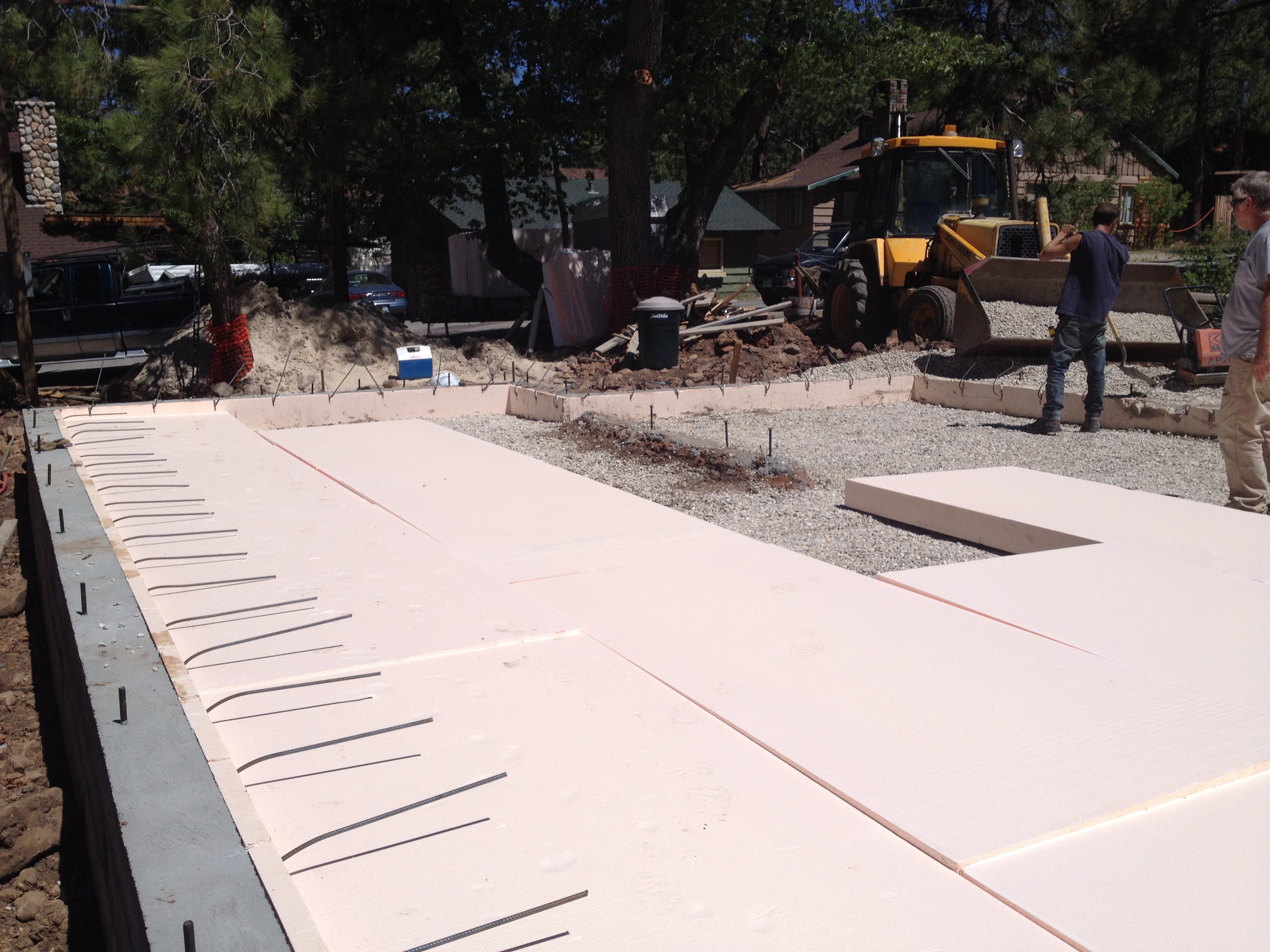
Passive solar works better when there is a large, insulated interior thermal mass that can absorb excess heat and re-radiate it when needed. In this case, my thermal mass was my foundation slab, 4 inches thick, covered with brown tile to absorb sunlight and insulated with 6″ of EPS foam underneath. Comprised of 330 cubic feet of concrete, as a thermal mass it can store around 7600 BTUs per Fahrenheit degree. This means as temperatures drop at night, the slab will act as a stored heat source, releasing 7600 BTUs of heat into the interior of the house for every degree in temperature drop. To put this in perspective, this is enough heat to keep the house comfortable, even when it is freezing outside. Of course, the concrete eventually cools off, but it can be recharged by sunlight and warm air from mechanical heating.

Design

Design — where do I begin? There are so many factors that play into designing a house, but the task takes on a whole new dimension when energy efficiency is a primary concern.

From the outset, the modest 50 foot x 100 foot lot size dictated a two story house to meet my 2000+ sq ft requirement. I also wanted to include a garage, even though it was a rarity in my neighborhood, because it would make life a lot easier in the winter. The siting of the house was pretty much determined by the trees I was keen on preserving: it would need to fit in between a large oak in the front of the property, and a small stand of mature pines in the rear. Other considerations included maximizing my limited views, letting in a lot of light, and limiting windows looking directly into neighboring houses.

From an energy perspective, I wanted to keep the shape of structure as simple as possible to make it easier to insulate and air seal — as close to a cube as possible, since that shape encloses the most volume with the least surface area (outside of domes and polygons). I also wanted to incorporate passive solar heating into the design, and have a good south facing roof space for a large solar array. Minimizing the window area was also a concern, both for controlling costs, and keeping the whole wall R values as high as possible.

The constraints that guided me toward initial designs included:

  • Create a simple shape for the building envelope.
  • Provide as many windows as possible on the south facade, and a wider roof overhang to shade them in the summer months.
  • Include a one car garage
  • Meet the City Planning Department’s guidelines for a design that fits into the character of this mountain community.
  • Achieve a functional, open floor plan, with an large connection between floors to allow for good air movement (since I wouldn’t be using a ducted heating system).
An early concept for the design in SketchUp, which I later refined to simplify the building envelope.

In the end, I came up with a two story design, roughly 26×48 for the house, with a gable roof and an attached 12×22 garage on the south side. Downstairs was open concept, and included the kitchen, dining are, living area, plus a half bath and a utility room accessible from the garage. The entry was open to the second story, which had a loft, laundry closet, two bedrooms, a guest bathroom, and a master bedroom with attached bathroom.

Floor-plan

I created an energy model of the house to determine its heating load under various outdoor design temperatures. This helped inform some of my design decisions in terms of window area and placement, and wall thickness to accommodate insulation. Although you need special software to run a complete building simulation, which can predict hour by hour energy performance, this was overkill for my needs. Instead, I created a manual steady state heat load calculation,  using an Excel spreadsheet to model the worst case winter temperatures.  Summers are mild so I didn’t need to worry too much about cooling demand.

The Process

My design process involved the following. First, I evaluated the site the determine what resources were available to reduce my heating load. Since I had good Southern exposure, I would use the sun to power solar panels (active solar), and also to heat the house with sunlight in the winter (passive solar). Next I designed the house to lose as little heat as possible. I did this by including as much insulation as possible, and also aggressive air sealing, ie reducing the amount of gaps in the walls to allow less warm air to leak out. Finally, as a last stage, I included a energy efficient heating system that provided just as much heat as predicted by the energy model, and was powered by the electricity created by the solar panels.


Framing

I originally planned on using an “Optimal Value Engineering” framing layout, in which walls would be framed 24” on center rather than the standard 16”, with single top plates, etc. But I was not able to get my engineer comfortable with the idea, and was too far along in the process to start over and find another.  However, I did order my windows in custom widths that fit the 16” on center framing, which didn’t have much of a practical effect on this project but was a successful experiment. This was one of my biggest regrets.

The exterior wall sections were of double stud construction – that is, they were composed of two parallel 2×4 walls, with a 2″ gap between them. This strategy allows for additional insulation, and a thermal break between framing members. The floor was supported by 16″ deep engineered trusses. The roof was composed of engineered scissor trusses, with a 4-12 top chord and a 2-12 bottom chord, separated by a 24″ raised “energy” heel to allow for a deep layer of blown cellulose insulation in the attic.

Virtual House

Parallel to the framing process, I decided to build a “virtual house” in a CAD program called Sketchup. Rather than just “drawing” the elevations and floor plans, I created 3D objects for framing members, and then assembled them to match the progress at the job site. This helped me to produce more or less exact lumber orders. It also helped me determine paths for plumbing and vent runs early in the process, to make sure everything would fit.

3Dview1

Lumber

Coming from academia and studying for my LEED certification, I had assumed finding FSC lumber (Forrest Stewardship Council certified) would be a no-brainer. However, I was shocked to discover nobody at the only lumberyard in town had even heard of this certification. I did find suppliers down the mountain, but the lead times were not workable for me and delivery charges were prohibitive. This was a bitter pill to swallow. So except for the OSB and plywood, my house uses non FSC-certified lumber.


Siding

Windows with Hardie siding butting right up against the frame
Windows with Hardie siding butting right up against the frame, cultured stone visible in the lower left. A special soffit vent at the top of the photos prevents embers from entering the attic.

Fire codes required me to use a non-combustible siding material so I went with James Hardie plank for most of the siding. As a fiber cement plank, it is non-combustible and also very durable in a harsh climate. Plus it matches the wood siding found in much of the neighborhood. In a few areas, as an accent, I used a cultured stone product.

Even though my climate is not a particularly wet one – most of the precipitation comes in the form of snow — I decided to use a textured house wrap under the siding, that afforded some drying potential and decent drainage. I believe a full rain screen, where the siding is kept off the housewrap using battens, would be overkill.

The product I used is called HydroGap from Benjamin Obdyke, that was very durable and had a texture layer that stood off of the housewrap approximately 1mm.  The housewrap went right over the OSB sheathing, and the small blue bumps allowed for vertical drainage and air movement.

Hydro Gap.300dpi
A closeup of the textured pattern on the HydroGap housewrap allows any water to drain all the way down the wall.

Rather than creating Hardie Board borders around the windows, I had my contractor run the siding right up to the edge of the windows. I thought this was a cleaner, more modern look with the brown window frames.

Insulation

My  goal was to insulate the entire structure as cost effectively as possible. Although I ended up spending much more on insulation that the typical code compliant house, my reduced (eliminated?) energy bills make this a good investment. I used a few techniques that are fairly novel in California – an insulated slab foundation and the use of rock wool batts in the walls. My overall insulation values were R25 under slab, R10 slab perimeter, R35 walls, R5 windows and R60 roof.

Foundation

Compared to the other areas of the building envelope, I probably went a little overboard with the 6″ under-slab insulation (R25) and could have saved a lot of money and headache by going with 2″ as opposed to 6″. This is because the ground under the house is rarely as cold as the air temperature in the winter, so you don’t need as much insulation there. First, the ground absorbs heat from the house, and does a reasonable job of holding it – as opposed to air where it is instantly lost. Second, if you dig down far enough, usually about 15-20 feet deep, the ground temperature stays constant, and equals the annual average air temperature. In Big Bear this is about 47 degrees F, which is a lot more than Big Bear’s Manual J design temperature of 7 degrees F. So you can get away with less insulation under the slab than in the walls and roof. But I really wanted to avoid having cold floors so I over-insulated the slab.

My foundation slab was insulated with 4’x8′ sheets of high density EPS foam, rated for below grade applications. I used 2″ around the perimeter and 6″ beneath the slab. Ideally, I would have had more insulation at the perimeter than under the slab, but structurally I didn’t have enough room.

IMG_2322
6″ thick type II EPS being laid out in preparation for slab pour. The 2″ perimeter layer can be seen in the background with rebar protruding.

Walls

In the walls,  I used a layered approach, sometimes referred to as “flash and batt”. I selected open cell spray foam as the first layer (applied against the sheathing between stud bays of the exterior wall) for two reasons. First, although it provided a level of insulation comparable to insulation batts (R13), it had the added benefit of serving as a good air barrier (at 3.5″ thick), and was also flexible enough to withstand settling of the framing without cracking. Second, because it was vapor permeable, it would allow my wall to dry to the outside, which is a desirable characteristic considering the well insulated wall would stay cold and I couldn’t rely on escaping heat from the building to dry out any moisture that happened to accumulate inside the wall. The installation went smoothly, however I was horrified at the amount of wasted foam that resulted from trimming the foam back to the depth of the studs. In the future I would explore using wet blown or dense packed cellulose instead of the spray foam.

IMG_2691
Spray foam being installed, with a trimmed bay next to an untrimmed bay. The installers filled alternating stud bays to allow for easier trimming.

The second layer of insulation in the walls was a continuous layer of 2” rock wool insulation from Certainteed Thermafiber rated at R 7.4, that filled in the gap between the two double stud walls. My final layer was 3.5” of Roxul brand rock wool (R 15) that filled the stud bays and framing cavities of the inner wall. Rock wool is much denser than normal fiberglass insulation –it is almost the consistency of a car wash sponge, and can be cut very easily with a serrated bread knife. It friction fits right into the cavities.

I was required by code to install a vapor retarder over the batts, so I selected a “smart” product from Certainteen called MemBrain. In a low humidity environment, it maintains a low vapor permeance. But if humidity goes above 60%, pores in the material open and allow moisture to escape, so the wall can dry out.

IMG_3355
Roxul brand rock wool insulation installed in the inner wall stud bays. Untrimmed foam insulates the rim joist above.

Attic

Finally, the attic space (which ranged from 2 feet to 4 feet high) was filled with 18″ of blown cellulose, for a rating of R60.

Heating, Cooling and Mechanicals

Before explaining how my house is heated, here is a quick overview of the status quo for heating system design in Big Bear, and for that matter, most of the country. First, build a house with the code minimum amount of insulation. Depending on how it is installed, this insulation may or may not be very effective at minimizing the amount of heat flowing out through the walls in the winter. But because the house is not tested for air leakage, a lot of heat will escape as the hot air simply flows around the insulation to the outside through gaps in the walls. So when a house is losing its heat so quickly, the only way to keep it comfortably warm is to pump a lot of heat directly in to each room. This is usually done using a furnace, which burns natural gas to create hot air, and a fan which blows the heated air through a series of ducts into each room. Depending on the furnace’s efficiency, it might be able to convert 80-96% of the gas’s energy into heat. But the blowers use a surprising amount of electricity, usually in the neighborhood of 800 watts to one kilowatt. Another downside to furnaces is that they usually have two speeds: full speed and off. This results in uncomfortable and sometimes noisy cycling on and off. Its like driving a car that doesn’t have a gas pedal, just a “80 MPH” button and an “off” button.

With my house, I started by creating a reasonably leak proof exterior shell, so warm air stays inside during the winter. A small ventilation fan ensures there is just enough fresh air in the house. I then included a higher level of insulation (including windows) than is required by California’s building code, which is one of the most strict codes in the country. Finally, I have a large insulated thermal mass in the house — the first floor slab — which can soak up a lot of heat during the day and radiate it at night. So because the house retains heat very well, you don’t need to blow a lot of heat quickly to the bedrooms because the don’t cool down very quickly. Instead of a furnace, I can use an alternative called a ductless mini-split heat pump to keep my house warm. Instead of generating heat, these units employ a refrigeration cycle to move heat from the exterior to the interior, or vice versa. Although its hard to believe, there is actually a lot of heat in the air even when its 0 degrees F outside. If you look at Kelvin, a temperature scale that measures absolute heat, total absence of heat is 0 K.  So even when it’s freezing outside, it is still 273 Kelvin out there, and your toasty interior is only slightly warmer at 294 Kelvin. Its just a matter of harvesting that heat and moving it indoors.

A mini split has several advantages:

  • Moving heat from the exterior air using a refrigeration cycle is a lot more energy efficient than making heat by burning nature gas. Even the most efficient gas furnaces are only 96% efficient, and that does not count the 800 Kw they use to move the hot air around. But a heat pump can surpass 300% efficiency. For every one unit of energy consumed, it can output 3 units of heat.
  • Minisplits use a variable speed fan which adjusts the heat output dynamically. This reduces or eliminates cycling on and off, and makes for very quiet operation.
  • Because the entire house is being heated as a system, you don’t need to install ducts to each room. Even if the bedroom doors are closed at night, the temperature generally won’t drop more than 3-4 degrees compared to the main living areas where the minisplit heads are located.
  • Minisplits run on electricity, so with some planning you can run your system entirely on solar energy.
IMG_5146
The exterior units – Mitsubishi mini-split heat pumps

My main heat source are two Mitsubishi Hyper Heat Mini Split heat pumps, each rated at 12,000 BTUs. These units are Energy Star rated, and very efficient at 26 SEER cooling and 12.5 HSPF (heating efficiency) which translates to a coeficient of performance over a 3. They can operate at full capacity down to 5 degrees, and still operate at 80% capacity in temperatures of -13 degrees. The ASHRAE Manual J design temperature for Big Bear  is “only” 7 degrees so these units will do well in this climate. As a bonus, they can run in reverse and provide cooling during the summer.

At the beginning of the project, I explored the possibility of an all electric house, even though natural gas was available at the site. However, after hearing some stories of winter blackouts lasting several days, I decided to install a direct vent natural gas fireplace as a back up heat source. (Plus, its nice to sit by a fire after a long day of skiing!) The model I selected used only outside air for combustion and at 18,000 BTUs, was capable of keeping the house nice and warm on its own, down to about 7 degrees outside temperature. It has a 62% fireplace efficiency ratio and a battery back up starter.

Domestic Hot Water

For hot water, I decided to use a condensing 97% efficient Energy Star rated tankless water heater from Navien. This direct vent appliance only uses outside air for combustion, and uses no standby energy when there is no hot water demand. This could come in handy for when the house is unoccupied in stretches. Also, since it has unlimited capacity (unlike a standard tank model), it will work well with the Jacuzzi tub. The house design isolates all plumbing to the southeast corner of the house. The upstairs bathrooms are adjacent, and directly above the downstairs bathroom and mechanical room. The kitchen is just outside the mechanical room. this makes for very short pipe runs, which will save water since you don’t need to wait very long for hot water to make it out of the tap. Also, all hot water lines were insulated.

Ventilation

For ventilation, I purchased a Swedish inline fan system from Resource Conservation Technologies, Inc. This fan moves 140 cfm with only 38 watts of power at 0.04″ static pressure which means 3.7 cfm/watt (easily meets Energy Star requirements). This “exhaust only” system expels a slow but constant amount of air from the house, to guarantee that there is a healthy amount of fresh air in the house at all times. This system is designed to meet ASHRAE 62.1 standards for ventilation. The air is exhausted from the bathrooms constantly, but motion and humidity sensors in the grill increase the airflow substantially when the bathrooms are being used.


Air Sealing and Ventilation

One of the ways to make a house more energy efficient is proper air sealing. As opposed to insulation, which slows the movement of heat through walls and other building materials, air sealing prevents heat loss through infiltration, the unplanned movement of air through the building envelope. With proper air sealing techniques, you can keep the conditioned (usually warm) air where you want it – in the house.

I planned on my house reaching a measured air tightness level of 1 ACH50 (about half the Passive House standard, but still 7 to 8 times tighter than normal construction). To reach this goal, I had to design an “air barrier” into the plan from the beginning. First I started with a simple shape. This has the primary benefit of minimizing surface area of the conditioned space relative to the volume of the house. But it also results in a more simple and easy to detail air barrier. Because I was using a slab foundation, that served as a very effective air barrier for the floor of the house.

IMG_2559
The flexible black building gasket can be seen filling in an irregularity in the frost wall concrete.

I used gaskets from Conservation Technology to seal the sill plates, which are where the framing meets the foundation. From there, the air barrier resided in the outer portion of the double stud wall, and was accomplished with open cell spray foam in the stud bays and with acoustic sealant between framing members. The windows were sealed with spray foam and backer rod.

IMG_2775
The ceiling air barrier (poly) connecting to the top plate of the outside wall with acoustic sealant.

The air barrier for the ceiling was a (mostly) continuous layer of 6 mil polyethelene sheeting applied to the ceiling (above the drywall). It was joined to the top plates using acoustic sealant, as the sheeting extended about 1′ down the walls. The ceiling air barrier was penetrated several times, even though I sought to minimize this by not using can lights, and also by using side sprayer fire sprinkler nozzles wherever possible. I sealed ceiling electric boxes with special EPS covers, spray foamed into place.

IMG_3759
An EPS cover from Energy Block foamed into place.

Then the attic above the ceiling was covered in 18” of blown cellulose insulation which is a decent air barrier on its own. Since I don’t have a need to access the attic except for emergency wiring or fire sprinkler access, I created a custom “attic hatch.” I attached 16″ of EPS to the back of a drywall panel, which friction fits into the opening (kind of like like a cork in a bottle) and rests on gaskets, and is finally sealed with a layer of paint.

Mechanical Ventilation

Because this house was to be fairly airtight, it required some kind of mechanical ventilation to guarantee enough fresh air, and meet the ASHRAE 62.2 ventilation standard. After looking in to an HRV / ERV, I decided to go with an inline exhaust fan that would constantly exhaust air from the bathrooms at low volume, and automatically switch to high volume based on motion and humidity sensors. The make up air would just come through the existing cracks in the wall, but the overall slight negative pressure in the house would keep any additional air from leaking out (infiltration). The fan I used is available from Conservation Technologies.

Solar Panels

From the onset, I knew that sunlight in this climate was a resource I wanted to use. Sunny, cool climates at high altitude are perfect for “active” photovoltaic systems. PV panels lose efficiency as they heat up, so cool weather is optimal. Plus at 6800 feet in altitude there is less atmosphere to reflect and diffuse sunlight than there is at sea level. Big Bear gets over 300 sunny days per year and is actually the home of a solar observatory, so this is an excellent location for solar.

My solar array is composed of eighteen 280 Watt American-made SolarWorld panels, for a total system size of 5.04 Kw. The system size was the maximum allowed by the local utility Bear Valley Electric, based on the size of my house. My system is connected to the electrical grid using a net metering system, so the meter spins backwards and generates a huge credit during the summer. Thanks to the use of microinverters, the system still generates power even when partially shaded, which happens in the early morning and late afternoon.

18 Solar World panels form a 5 KW array, as seen by a small drone

Solar was a no-brainer from a financial standpoint. The system costs about $20,000. However, after a Federal Tax credit of $6000 and a state rebate of $5000, the net system cost is only $9000. Electrical rates from Bear Valley Electric are much higher than national averages, about $0.36 per kwh. That means my system should generate close to $2000 worth of electricity per year.


Windows

Windows can be a complicated decision, especially for energy efficient houses. In addition to the normal concerns over price, style, and durability, you have an even more important criteria to contend with — energy efficiency, which has many dimensions, including U factor (overall and center of glass), number of panes, air leakage rates, emissivity (“Low-E”), solar heat gain coefficient (SHGC), and inert gas fillings between panes (usually argon). In addition, I had two requirements based on my location. One was local fire codes required all the windows to use tempered glass. Another was the high altitude (6700 feet) made ordering windows filled with argon impractical, so I decided to go with air filled IGUs at a slightly lower thermal performance.

For the window material, my top choices were fiberglass and uPVC. These materials hold up very well to the elements and also the have very similar expansion and contraction characteristics to glass, so they are more durable in harsh climates with large temperature fluxuations.

I ended up considering a wide range of windows, from very high performance Canadian and European manufacturers with nearly air tight Tilt-and-Turn designs, to a value-priced local company (Milgard) that had a manufacturing facility about an hour or so away. I had bids ranging from $5,000 to $25,000, albeit for very different products.

In the end I went with triple-pane Pella 350s, because they offered a high performance product at a reasonable price. Even though they only came in PVC frames, they featured excellent triple pane IGUs at 1 – 1/4″ thickness (proper spacing for good energy efficiency) with R5 insulating capability, and a variety of coating options that would allow me to have high SHGC (their “NaturalSun” coating) on my south facing windows. I could also order them in custom widths to fit within standard framing intervals.

Pella 350 windows taped to the Hydrogap housewrap.
Pella 350 windows taped to the Hydrogap housewrap. This is the east corner of the south wall, where a third of my windows were located.


My final window U values ranged from 0.26 to 0.18 (roughly R4-R5). While this is pretty good for a window, it is poor compared to my roof (R60) and walls (R35). So my goal was to use as few windows as possible, except on the south entry, where special high heat gain glass (0.5 SHGC) allowed in slightly more heat from the sun than they leaked out during the heating season. Of my 2600 sq ft of total wall surface area, only about 300 sq ft of that was windows, and 127 sq ft of the windows were designed for passive solar gain and located on the southeast wall.

I ordered the PVC frames in a dark brown exterior color that would work well with the design of the house. The windows were carefully flashed to the Benjamin Obdyke HydroGap housewrap to prevent water intrusion. The sill pans were created using peel and stick flashing, HydroGap tape and HydroCorner molded corner inserts.

My 96 sq ft of exterior doors were Masonite brand doors with U values ranging from 0.15 to 0.23 (R4-R7).

Foundation

My initial concept for the foundation was a frost wall, with a concrete slab resting on a continuous layer of foam insulation. Not only is a slab air tight, especially compared to a subfloor over a crawlspace, but it also serves as a thermal mass. If that mass is thermally isolated from the ground, it can help regulate indoor temperatures and even supply heating to the house when paired with appropriately shaded south facing windows.

Wanita-Detailed-Wall-Section
Detailed wall section showing R8 perimeter EPS insulation and R24 below slab.

Step one was to dig out the foundation frost walls, which had to be 3′ below grade so that they were below the frost line. Once the frost walls were formed and poured, the next step was pouring the slab. I had designed the slab so it was insulated with 2” of EPS along the perimeter and 6” underneath. I would have preferred more insulation at the perimeter, but since I didn’t want to leave the EPS exposed on the interior, that was all the room I had to work with, even with 9″ thick walls.

Finding “small” quantities of high density (Type II or greater) EPS insulation rated for subslab uses is not easy, when you live in warm, sunny San Diego, for the simple fact that nobody insulates slabs out here. But eventually I found a distributor which delivered to Big Bear. I used Type II EPS, with a compressive strength of 8.8 psi at 1% deflection. The slab resting on the EPS weights about 0.35 psi so there is a comfortable margin there.

Although my plans called for optional rebar pinning the slab to the frost walls, my inspector required it because of the clay content in the soil. And although structurally it was the right call, I was worried about the rebar penetrating the EPS, and short circuiting my continuous layer of insulation.

However, it wasn’t as big a deal as I had feared. EPS has an R-Value of R4 per inch at 7 degrees F, which is the Manual J design temp for Big Bear. Because the slab is only 4” thick, the total surface area of the perimeter EPS is only 50 sq ft. So with a U value of 0.13 and a delta T of 60 degrees F (67 – 7), the EPS would lose 375 BTU per hour. The 1/2” rebar penetrates the insulation 98 times, but each cylindrical bar has a surface area of only 0.75 sq in, so the total surface area for all the bars is only 0.5 sq feet. But since the R value of steel is 0.0381, I’d still lose 417 but/hr through the steel, so it cuts the performance of my perimeter slab insulation in half. However, the steel and EPS combo still outperforms plain concrete by a factor of 15.

IMG_2324First the perimeter 2” insulation was installed on the inside of the frost walls, to a depth of 24″. Then the pad was compacted, and 2” of crushed gravel was applied. The 6” thick 4’x8′ EPS panels were installed in a brick pattern. Holes around plumbing penetrations were sealed with spray foam. Then a sheet of poly was spread over the EPS before the slab rebar was attached to the frost wall rebar, and finally the concrete was poured into what amounted to a giant EPS form.

Air Sealing

I found the tops of the frost walls to be pretty rough, and even though I was planning on using a sill gasket from Conservation Technologies, I decided to use an angle grinder to smooth and flatten the concrete under my sill plates as much as possible.

Foundation bolt in frost wall, with rough concrete surrounding it.
Frost wall smoothed out with angle grinder, to form a more air tight seal with building gasket.